Tee sections
NSC 21
Technical Digest 2019
The overall depth of the effective section is therefore
18 × 0.88 × 8.1 = 128.3 mm. The dimensions of the effective section are
shown in Figure 2. Calculations are required to determine the position of
the neutral axis (accounting for the root radii if doing a ‘proper’ job!), and
calculating the effective elastic modulus of the section. The effective elastic
modulus is calculated as 36.3 cm3.
w = 3 6 . 3 = 0.18
199
Then LT = 0.648 × 1.05 × 123.8 × 0.18 = 35.7
Following the same process from B.2.1, the bending strength,
pb = 339 N/mm2
The buckling resistance moment Mb = 339 × 36.3 × 10-3 = 12.3 kNm
Method 3 – BS EN reduced stress method
The ratio for local buckling is defined differently in the Eurocode, which
species c/t as the dimensions of the outstand, not overall depth.
(227.2 – 13.3 – 10.2)
c/t = = 25.2
8.1
The limiting value depends on the stress ratio between the stress at the
tip of the web, and at the root radius (refer to Table 5.2 in BS EN 1993-1-1).
To evaluate the limit, BS EN 1993-1-5 must be consulted to calculate the
buckling factor, kσ .
If the neutral axis is at 58.4 mm from the face of the flange (from section
property tables), the stress ratio may be calculated from the dimensions
shown in Figure 3.
= - 3 4 . 9 = -0.207
168.8
From Table 4.2 of BS EN 1993-1-5, then
kσ = 0.57 – 0.21ψ + 0.07ψ2
kσ = 0.57 – 0.21 × (-0.207) + 0.07 × (-0.207)2 = 0.616
Back in BS EN 1993-1-1 Table 5.2,
the limit is 21 k = 21 × 0.81 × 0.616 = 13.3
25.2 > 13.3, so the section is class 4 (not surprisingly, given the BS 5950
classification)
To ensure the section remains class 3, the reduced design strength
is given by 25.2
235
( )2 = 100.5 N/mm2 21 × 0.616
Mcr must be calculated, using the gross properties. Ltbeam is a convenient
software to use. With a UDL causing compression on the web, Mcr = 67 kNm.
Verification then proceeds in the usual way, using the general case of clause
6.3.2.2. A tee section is taken to be an “other cross section” in Table 6.4. The
intermediate values are therefore:
λLT = 0.41
αLT = 0.76
φLT = 0.66
χLT = 0.84
and finally MbRd = 9.5 kNm
Method 4 – BS EN effective section method
Having found the section is class 4, the effective length of the web may be
determined from BS EN 1993-1-5.
If kσ = 0.616 then from clause 4.4(2)
p = b / t = = 1.39
28.4 k
25.2
28.4 × 0.81 × 0.616
Because λp > 0.748 then
= = = 0.622 p – 0.188
p
2
1.39 – 0.188
1.392
The effective length of the web from the neutral axis is therefore
0.622 × 168.8 = 105 mm and the overall depth of the effective section is now
163.7 mm.
This change of section means that the original assumptions about c/t
ratio, position of neutral axis etc are now invalid. The process must be
repeated (by spreadsheet preferably!) until a final solution is found. A final
solution is found when there is no further reduction needed to the web (i.e.
all the reduced section is effective). This happens when ρ = 1 (no reduction),
which, with reference to BS EN 1993-1-5, happens when λp =0.748
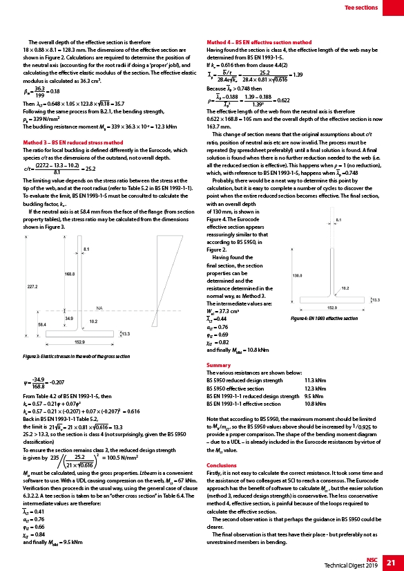
Probably, there would be a neat way to determine this point by
calculation, but it is easy to complete a number of cycles to discover the
point when the entire reduced section becomes effective. The final section,
with an overall depth
of 130 mm, is shown in
Figure 4. The Eurocode
effective section appears
reassuringly similar to that
according to BS 5950, in
Figure 2.
Having found the
final section, the section
properties can be
determined and the
resistance determined in the
normal way, as Method 3.
The intermediate values are:
Wel = 37.3 cm3
λLT =0.44
αLT = 0.76
φLT = 0.69
χLT = 0.82
and finally MbRd = 10.8 kNm
Summary
The various resistances are shown below:
BS 5950 reduced design strength 11.3 kNm
BS 5950 effective section 12.3 kNm
BS EN 1993-1-1 reduced design strength 9.5 kNm
BS EN 1993-1-1 effective section 10.8 kNm
Note that according to BS 5950, the maximum moment should be limited
to Mb /mLT , so the BS 5950 values above should be increased by 1 ⁄ 0.925 to
provide a proper comparison. The shape of the bending moment diagram
– due to a UDL – is already included in the Eurocode resistances by virtue of
the Mcr value.
Conclusions
Firstly, it is not easy to calculate the correct resistance. It took some time and
the assistance of two colleagues at SCI to reach a consensus. The Eurocode
approach has the benefit of software to calculate Mcr , but the easier solution
(method 3, reduced design strength) is conservative. The less conservative
method 4, effective section, is painful because of the loops required to
calculate the effective section.
The second observation is that perhaps the guidance in BS 5950 could be
clearer.
The final observation is that tees have their place - but preferably not as
unrestrained members in bending.
Figure 3: Elastic stresses in the web of the gross section
Figure 4: EN 1993 effective section