Commercial
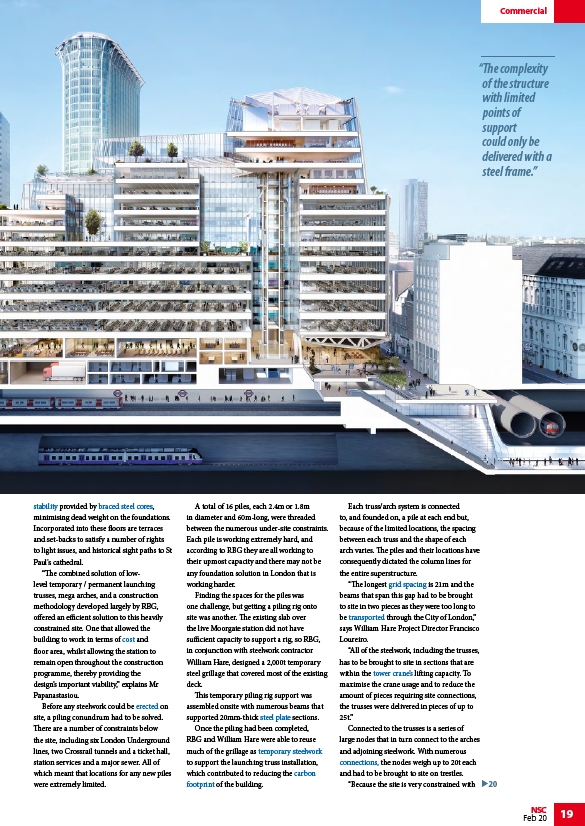
“The complexity
of the structure
with limited
points of
support
could only be
delivered with a
steel frame.”
20
20
NSC 19
Feb 20
stability provided by braced steel cores,
minimising dead weight on the foundations.
Incorporated into these floors are terraces
and set-backs to satisfy a number of rights
to light issues, and historical sight paths to St
Paul's cathedral.
“The combined solution of lowlevel
temporary / permanent launching
trusses, mega arches, and a construction
methodology developed largely by RBG,
offered an efficient solution to this heavily
constrained site. One that allowed the
building to work in terms of cost and
floor area, whilst allowing the station to
remain open throughout the construction
programme, thereby providing the
design’s important viability,” explains Mr
Papanastasiou.
Before any steelwork could be erected on
site, a piling conundrum had to be solved.
There are a number of constraints below
the site, including six London Underground
lines, two Crossrail tunnels and a ticket hall,
station services and a major sewer. All of
which meant that locations for any new piles
were extremely limited.
A total of 16 piles, each 2.4m or 1.8m
in diameter and 60m-long, were threaded
between the numerous under-site constraints.
Each pile is working extremely hard, and
according to RBG they are all working to
their upmost capacity and there may not be
any foundation solution in London that is
working harder.
Finding the spaces for the piles was
one challenge, but getting a piling rig onto
site was another. The existing slab over
the live Moorgate station did not have
sufficient capacity to support a rig, so RBG,
in conjunction with steelwork contractor
William Hare, designed a 2,000t temporary
steel grillage that covered most of the existing
deck.
This temporary piling rig support was
assembled onsite with numerous beams that
supported 20mm-thick steel plate sections.
Once the piling had been completed,
RBG and William Hare were able to reuse
much of the grillage as temporary steelwork
to support the launching truss installation,
which contributed to reducing the carbon
footprint of the building.
Each truss/arch system is connected
to, and founded on, a pile at each end but,
because of the limited locations, the spacing
between each truss and the shape of each
arch varies. The piles and their locations have
consequently dictated the column lines for
the entire superstructure.
“The longest grid spacing is 21m and the
beams that span this gap had to be brought
to site in two pieces as they were too long to
be transported through the City of London,”
says William Hare Project Director Francisco
Loureiro.
“All of the steelwork, including the trusses,
has to be brought to site in sections that are
within the tower crane’s lifting capacity. To
maximise the crane usage and to reduce the
amount of pieces requiring site connections,
the trusses were delivered in pieces of up to
25t.”
Connected to the trusses is a series of
large nodes that in turn connect to the arches
and adjoining steelwork. With numerous
connections, the nodes weigh up to 20t each
and had to be brought to site on trestles.
“Because the site is very constrained with
/Concept_design#Structural_options_for_stability
/Concept_design#Concrete_or_steel_cores
/Cost_of_structural_steelwork
/Construction#Steel_erection
/Steel_construction_products#Flat_products_-_plates
/Construction#Temporary_works
/Life_cycle_assessment_and_embodied_carbon#What_is_embodied_carbon.3F
/Life_cycle_assessment_and_embodied_carbon#What_is_embodied_carbon.3F
/Concept_design#Floor_grids
/Fabrication#Handling_and_transportation
/Construction#Tower_cranes
/Simple_connections