50 & 20 Years Ago
Undercover work on Maplin

Although the date for construction of Maplin has been postponed quite recently it still seems that the airport will be built. Not so long ago, however, there was much greater urgency required in many investigations needed before actual construction could begin. Among the many projects under way was the need to determine the effect of the reclamation on tidal levels and estuaries. New facilities were required to examine this question and these are described in the following notes.
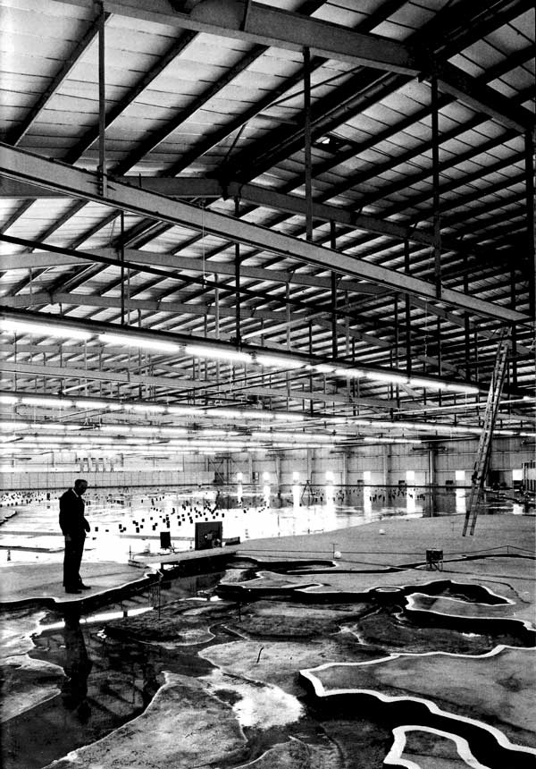
When work on land reclamation for Maplin Airport and seaport starts, much of the material required will be pumped from the surrounding estuary. In order to determine the best plan shape of the area to be reclaimed, and to study the effects of reclamation on tidal levels and the possibility of consequent alteration to surrounding channels and estuaries, the DOE commissioned the Hydraulics Research Station to build a model of the estuary at Wallingford, Berkshire.
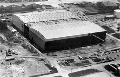
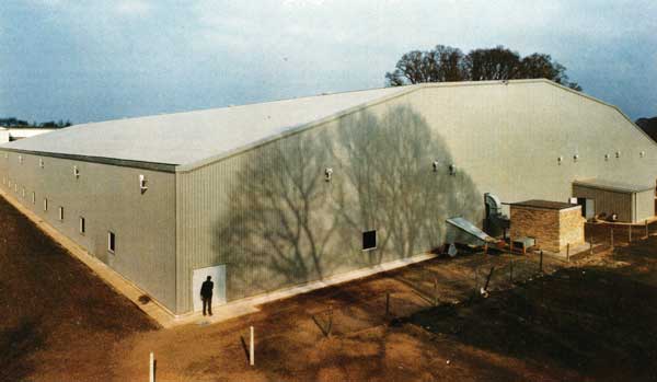
Built to a scale of 1/1000 the model represents an area extending from Woolwich Reach to Felixstowe in the north, to Margate in the south-east and thence seawards for some 48km. The model proved to be the largest of its kind ever produced in the UK and called for a somewhat unusual building in which to be housed. No internal supports which might interfere with the model were to be allowed, and furthermore the construction programme called for the building of the model and the erection of the superstructure to proceed at the same time and to be completed in no more than twelve weeks.
After calling for tenders, the Property Services Agency in July 1972 appointed Taylor Woodrow as main contractors and Conder International as sub-contractors for the design, fabrication and erection of the steel-framed envelope.
The requirement was to produce a structure which would provide a building completely clear of internal supports, of the following dimensions:
- 70m span
- 103m in length
- 6m height to eaves
A further problem that existed was that the structure would be erected on very poor ground and therefore over-turning moments at the bases were not acceptable and horizontal forces had to be kept to a minimum. Various solutions were considered to provide the above requirements and also to produce a building of pleasing appearance in view of the nature of the site.
After considering many alternatives, including clear span portals and lattice girder profiles, the tied mansard portal frame proved to be the most economical scheme in the use of steel. An attractive appearance both internally and externally ensued and also the forces resulting at the bases were of absolute minimum. This was the scheme that was finally selected.
Tied Mansard construction complicates the design of the rafters as both moment and axial force have to be considered in the selection of members. After investigation two conditions of loading were shown to be critical:
- (i) dead load+ super load
- (ii) dead load + wind load + internal suction
Under the first condition of loading the rafters induce moment and axial compression with resulting tension forces in the horizontal tied member. Vertical load was kept to a minimum by the choice of metal sheeting to the roof but this was shown to be a handicap when considering wind uplift and it was therefore necessary to ensure that the tie could take compression forces due to reversals of wind uplift in order that an economic rafter section could be provided and to reduce the overall sway of the structure. In order that the tie could act in compression longitudinally members were provided connecting the tie member into an effective compression system. The rafters and ties were spliced for delivery and erection requirements and HSFG bolts were used throughout to produce the necessary strength.
Large clear spans of this nature will, of necessity, deflect and resultant deflections should be well within those allowed for in BS 449 if movement at the apex is to be kept within reasonable limits. Plastic design was used throughout and the structure was checked by computer in order to ascertain the predicted deflections. The frame was then detailed and erected such that the position of the apex of the structure was pre-described and pre-set, i.e. when subsequent loading was induced the apex and stanchions deflected to the final position.
A system of tension bracing across the roof ensured that the considerable forces which can be induced are carried to the ground without inducing perceptible longitudinal deflection and this was also proved to be the most economical method.
Erection stresses were also checked by computer as it was not possible to provide cranage within a limited area, as work on the ground floor slab was being carried out concurrently.
The building contains approximately 300 tonnes of steelwork and, complete with cladding, ventilators, doors and windows (but excluding foundations and floor slab), was designed, fabricated, erected and clad in approximately twenty-four weeks at an approximate cost of £100,000 (approximately 130p per sq.ft plan area). Previous experience of this type of frame combined with an existing computer programme for analysis enabled Conder to achieve this programme.
The main tied arch frames at 7·5m centres weigh approximately 12·5 tonnes each and were individually assembled on timbers over the floor slab and model area and hoisted into position with two cranes running along pre-arranged strips of the floor slab.
The project was pre-planned in four continuous phases and programmed throughout to enable the building and civil engineering operations to continue in conjunction with the construction of the model by the client.
The client was given access to part of the basin floor slab for construction of the model seven weeks after possession of site by the main contractor and the whole floor basin was available sixteen weeks later.
The main contractor was directly responsible for site excavations, building foundations, drainage, watertight floor basin and slab construction, water supply to building and outfall to the River Thames, hardstanding, paved areas and external surfacing and for co-ordination of the work of the building sub-contractor. Tree planting was arranged under separate contract.
Lighting, heating and power supply were installed under separate direct contracts and the ancillary accommodation including the fan house and miscellaneous items was carried out under term contract by the DOE Area Office, Abingdon.
At the tender stage Conder were in competition with other designs, including the use of space frames. Important factors in the final choice were cost and the tight programme required. As noted above, the building was economical and the construction programme was realized – both achieved through the use of standardized techniques in design and fabrication. The building has one of the largest clear spans of its type in the UK.
Client: Directorate of Social and Research Services of the Property Services Agency Department of Environment
Main Contractor: Taylor Woodrow Construction Ltd Steelwork Contractor: Conder International Ltd