Projects and Features
Extending the Empress State Building

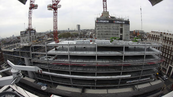
The 30 storey Empress State Building South Extension during
construction (Photography: Morley von Sternberg)
An existing thirty-storey concrete office block in west London has been extended both vertically and horizontally in steel. Dominic Bettison and Bjorn Watson report.
FACT FILE: The Empress State Building, London
Client: Land Securities
Architect: Wilkinson Eyre Architects
Structural engineer: Anthony Hunt Associates
Steelwork contractor: William Hare
The Empress State Building is a 30-storey concrete-framed building constructed in the early 1960s. The building plan is a distinctive ‘Y’ or tricorn shape is very inefficient by modern space planning standards. Located on the west side of London in Earls Court, the 100m high building at one stage briefly, and for a few months only, had the status of London’s tallest building. However the Empress State is still the tallest significant building in west London and boasts fantastic panoramic views of the Thames valley.
The Ministry of Defence (MoD) took over the building during its construction and as the building was the HQ for the British Admiralty, and was the centre of operations for the Falklands War, perhaps not surprisingly, the MoD had maintained a low profile for it and few people noticed it on the skyline overshadowing the Earls Court Exhibition centre.
Wilkinson Eyre was appointed in 2001 as architect by the building’s owner Land Securities, with Anthony Hunt Associates (AHA) as structural engineer. The brief required the building to be refurbished and extended to provide 450,000ft2 of modern, flexible, serviced office accommodation and to radically improve the building’s environmental efficiency. Speed of construction was an important consideration for the client and a very ambitious programme of 76 weeks (a completed floor every two weeks) was set and adhered to by the construction team headed by Bovis Lend Lease.
The brief and initial design proposals required:
- Refurbishment of the existing office space at 1st to 26th floors.
- Horizontal extension of the existing building at the south façade to increase office space from 2nd to 26th floors, with a roof terrace at 27th floor
- Vertical extension of the existing building to increase office space at 27th to 29th floors, with a central revolving bar at the 30th floor
- Formation of a two-storey circular ‘drum’ extension enclosing the base of the existing building. On the south side, the drum was to form a double-height, glazed reception area, with a roof terrace at 2nd floor. The north-west drum segment was to contain a café on the ground floor with office space above.
- A new underground boiler house on the north boundary of the site with a service tunnel connection to the existing building basement.
- A new Piazza Building on the south boundary, to provide leisure facilities(restaurant, swimming pool, health club,gym, etc) on two storeys with a limited plant basement.
- A new Entrance Building fronting Lillie Road with office space on three storeys.
- Re-landscaping (both hard and soft) the site.
The building’s existing plan has a central reinforced concrete lift and stair core with WC facilities, and further stairs and lifts located at the end of each wing. Internally the plan has been re-organised locating the WCs from the external cores and grouping them around the central core. This creates space for three dedicated plant rooms on each floor which in turn provides flexibility by allowing the floor plate to be sub-divided into three tenancies each with dedicated servicing.
The south facade extension
The most challenging modification both structurally and architecturally to the typical floor, however, has been to extend the main south portion of the floor plate by 5.5m. The extension provides pure net additional floor space. The extended floors rise from the 3rd to the 26th floor with the lid of this extension forming an external terrace for the 27th floor. One of the key architectural aspirations was to maximise physically and psychologically the 10ft floor to floor height. The ceiling heights, which are already low by modern standards, needed to allow for a slim raised access floor (75mm) and soffit-mounted chilled beams. Due to the restricted floor-to-ceiling height it was decided that suspended ceilings were inappropriate. Instead radially mounted, soffit-hung chilled beams were purpose designed.

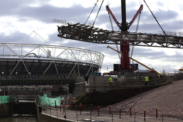
South Extension new structure during construction. (Photography: Morley von Sternberg)
These supplied all tempered fresh air, lighting, sprinklers, smoke detection and PA system to the floors. The frame was erected floor by floor and effectively formed a creeping working platform. This allowed the south elevation’s upper floors’ existing cladding to be stripped off and the necessary structural connections and modifications to take place without employing dedicated scaffolding. These additional benefits combined with the intrinsic speed of the composite frame enabled fast construction with roughly a floor per week erected.
This type of construction also highlighted issues of differential tolerance between the 1960s in-situ concrete frame and the tighter tolerances of the modern steel frame. Careful design and analysis of survey information and calculations ensured that the floors did not creep relative to one another as the steel frame rose up the building. There was little margin of error available for mis-alignment of floors as both the raised floors’ zones and overhead services had to run through without interruption from the existing structure into the new. The use of shadow gaps was therefore widely employed in order to introduce tolerance between elements particularly above the 9m chilled beams as they spanned from old to new.
It has been said that this is probably the tallest example in the world of a steel frame tied to an existing concrete frame. Whether this is the case or not this particular element presented huge technical problems for all involved which were ultimately successfully overcome.
Environmental improvements

Exploded axonometric (Drawing: Wilkinson Eyre Architects)
A major objective of the refurbishment was to greatly improve the environmental efficiency of the building. The original single-glazed cladding to all elevations did not have any insulation or any form of solar control. All facades were therefore re-clad with modern high performance cladding systems using solar control double glazing, thermal breaks and brise soleil shading.
The south façade was subject to enhanced treatment due to its orientation and prominence. A full height ‘shield’ of external aluminium brise soleil louvres has been incorporated into the cladding system. Without the aid of scaffolding it was impossible to install a standard ‘stick type’ curtain walling system. Instead pre-fabricated and pre-glazed storey height cladding panels were installed to the south.
These panels came pre-assembled with their external walkways and full height horizontal aluminium brisesoleil louvres.
Upper floors: upwards extension
The building had originally had a reduced-size floor plate at level 27. Above this protruded an unusual structure, pod-like in appearance, which came to be known as the ‘crows nest’. This structure effectively set the overall 100m height of the building and it was stipulated by the local planners that any new accommodation should not exceed this.

View of upwards extension structure (Photography: Giles Barnard)

The distinctive ‘Y’ or tricorn shape is clearly visible (Photography: Courtesy of Bovis Lend Lease – Christof/Ben Bovis)
All existing concrete structure from level 27 and above was demolished. The roof top plant was cleared away and re-located at ground level in part of the new double height ‘drum’ element. It was then possible to add accommodation at roof level in the form of a three-storey lightweight steel and glass structure which was crowned by a fully glazed drum structure housing a revolving bar. The facades to floors 28 and 29 incline dramatically outwards.
The new structure took the shape of the existing floors below but was pulled back from the edge of the building on the east and west elevations in order to express it as a new addition. This strategy however generated complexities for the structural engineers as the CHS steel columns of the new addition could not directly transfer load to the existing RC columns below. Carbon fibre stiffening plates bonded to the existing slab were originally considered but the time and money available combined with the specialist nature of the work discounted this solution. Instead a transfer structure consisting of pre-cambered beams forming a steel grillage was installed in order to re-direct loads to the existing columns. The steel grillage was ‘hidden from view’ by an extra deep raised floor zone with the services running through holes formed in the steel beams.
Above this element the floor plates were constructed from CHS steel columns supporting beams carrying permanent metal deck shuttering with a structural topping. The existing central and perimeter cores containing lifts, escape stairs and service risers, formed from reinforced concrete, were extended upwards and used to tie back and stabilise the new structure. Owing to the need for quick construction demolition, forming of the RC work, and erection of the new structure had to take place in parallel in a very restricted area 27 storeys above ground level – a major feat of construction and planning.
Structural aspects: South façade extension
The existing reinforced concrete structure has a floor-to-floor height of 3.05m and the refurbishment proposals were to provide a limited 75mm false floor with chilled beams to the existing soffits to maximise the clear headroom. The challenge therefore was to achieve a structural floor plate no thicker than the existing 8” slab to maintain the proposed raised floor zone and soffit levels.
The solution was to provide an arrangement, applying from 3rd to 27th floors, that comprised a braced steel frame supporting precast pre-stressed concrete planks laid parallel to the existing and new façades. The precast planks are topped with a composite reinforced screed, which provides in-plane stability via post-drilled connections to the existing slab. The planks are supported on fabricated asymmetric I-section beams, which span radially between H-section columns tied to the existing façade columns and H-section columns at the new façade. The edge beam at the new façade supports the glazing and the proposed external maintenance walkways and louvers. It is therefore subjected to torsional loads and so a rectangular hollow section (RHS) beam was provided.
A further challenge was to ensure compatibility between the new and existing floors taking into account the differential vertical movement of the new steel frame and the existing concrete subject to varying dead, superimposed and temperature loads during both the construction and in service. This movement had to be accommodated while ensuring that the new extension was adequately tied to the existing structure. A vertical slip joint was therefore detailed at the new-to-existing column tie and the new-to existing slab connection is partially released near the columns.
Upper floors: upward extension
With the exception of the central and apex core, most of the existing reinforced concrete super-structure, including the 30th floor observation room, was demolished down to the existing 27th floor slab.

View of upwards extension viewing platform (Photography: Morley Von Sternberg)
The superstructure for the 27th to 29th floors comprises a braced steel frame supporting a bespoke composite ‘Slimflor’ solution. This floor structure utilises a 215mm deep lightweight concrete slab composite with 100mm deep permanent metal decking. This spans parallel to the façades and is supported on fabricated asymmetric I-section beams (FASB). The FASB beams are supported on CHS columns at the façades and steel ‘cellform’ spine beams along the central spine, which in turn span between CHS columns. The slab tied to the central and apex cores provides the in-plane stability.
The existing 27th floor slab and perimeter beams are unable to carry the new perimeter column loads from above. Therefore, along the east and west façades, where the roof extension building line steps in, a grillage of H-section beams is provided to transfer the new column loads to the existing columns below. At the south façade, where the roof extension building line coincides with the existing façade below, the existing perimeter beam was demolished and re-constructed in reinforced concrete to transfer the new column loads to the existing columns.
At the 30th floor level, the bespoke ‘Slimflor’ construction is replaced with H-section beams supporting cold-formed purlins and lightweight roofing. These beams extend outwards, as cantilevers over the perimeter columns, to support the façade cleaning cradle rails. Within the central area, the H-section beams, together with isolated I-section and ‘cellform’ beams, support a 200mm thick lightweight concrete composite slab on 70mm deep permanent metal decking and the subframe for the revolving bar floor. Springing from this level, extensions to the core walls, together with external fabricated plate columns around the bar perimeter and, internally, CHS and H-section columns, support the support the bar roof and a central open-top plant room.
Existing structure modifications: Loading down
Careful analysis of the existing and proposed loads demonstrated that the removal of the existing finishes and floor screeds equates at ground floor level to the load of the proposed roof extension. Therefore in general the loads applied to the existing foundations are unchanged.
Overall dynamics
A dynamic analysis of the existing frame revealed that the structure exhibits two principle modes of oscillation, a translational and a torsional, at approximately the same fundamental frequency, about 0.5Hz. However, the horizontal deflection of the existing structure subject to the equivalent static wind load is very small. Therefore the dynamic response of the existing structure is unlikely to cause concern to the occupants.
New foundations
At the existing south façade, the loading down analysis revealed that the existing piles could not resist the proposed loads without significant and unpredictable settlements. Therefore, to limit the increased loads on these piles, new external piles and cantilever ground beams, counterbalanced by the new south façade columns, were used to support the additional loads in the existing columns. The new piles are large diameter, bored, cast-inplace concrete piles and the ground beams are extremely stiff reinforced concrete beams.
Credits
Dominic Bettison is an associate at Wilkinson Eyre and was project associate for the Empress State. Bjorn Watson is a director at Anthony Hunt Associates based in their Cirencester office. He was formally a director of YRM