50 & 20 Years Ago
50 Years Ago: New Ascot Grandstand

View of the completed stand
Steelwork was used for the frame of the new Queen Elizabeth II Stand at Ascot, which was opened last June after a construction period of only ten months, because such a tight building programme demanded as much prefabrication of materials as possible before work commenced on site.
The stand consists of two main portions. The main section facing the course is 560 ft. long, 80 ft. deep and an average height of 74 ft.; there is a circulation area centrally at the rear one-third as long. Two complete joints either side of the circulation block divide the stand into three; 1,200 tons of steel were used.

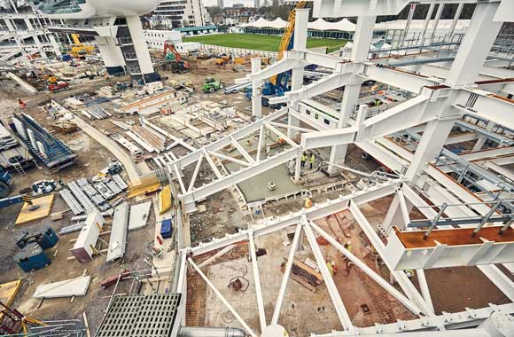
Work in progress on the Ascot Grandstand. showing terrace rakers, box balcony cantilevers and roof construction of galvanised trusses and plated girders – the latter with manholes for maintenance access
The main section of the stand was designed on a fully rigid basis, all the intersecting connexions between columns were shop-welded, and side joints where they were required, were bolted and positioned at points of minimum moment, i.e. mid points of column and third points of beams. In order to reduce the number of site joints complete sections comprising columns of two bays for two storey heights together with connecting beams and cantilevers were fabricated in the shop: these sections were fabricated in the shop up to the maximum size possible for handling and transport.
Universal Beam and Column sections to B.S.15 were employed almost exclusively for the job and where some full strength joints required bolts, high-strength friction grip bolts were used.
The steelwork was unpainted and protected by concrete cladding 2 in. over the sections. The 40-ft cantilever roof structure was hot dip galvanized to save weight. The cantilevers were generally of lattice construction except where they supported the Tic-Tac platform, and plate girders of the same outline were used.
The design loading for the structure was 100 lb./sq. ft. except in the upper private dining-rooms and boxes where it was 80 lb./sq. ft. The steelwork supports precast concrete floors and terraces on a 20-ft. frame spacing with front rakers at 10-ft. centres. Where possible all pre-cast work was of hollow construction to reduce dead load.
The columns were designed as pin based and two bolts used at each foundation. Because of the complexity of the rigid design under wind action, there being columns of 4-storey height at the front and six at the rear, an electronic computer was used for this analysis. These calculations showed that usual assumptions of shear distribution were inadequate for such a shape.
The lightning-protection system of the structure used the main frame as the conductor from roof to ground level. The copper tapes were connected to several stanchions in parallel at eaves level; care was taken to insulate the tapes from the zinc galvanized roof-work. At foundations level tapes were connected to the stanchions just above the base plates and connected to one another as a ring main.